Friction and Fittings

How Flow Loses Energy: Friction and Fittings in Real Systems 🚰💡

Views in the last 30 days: 12

Estimated read time: 7 minute(s)

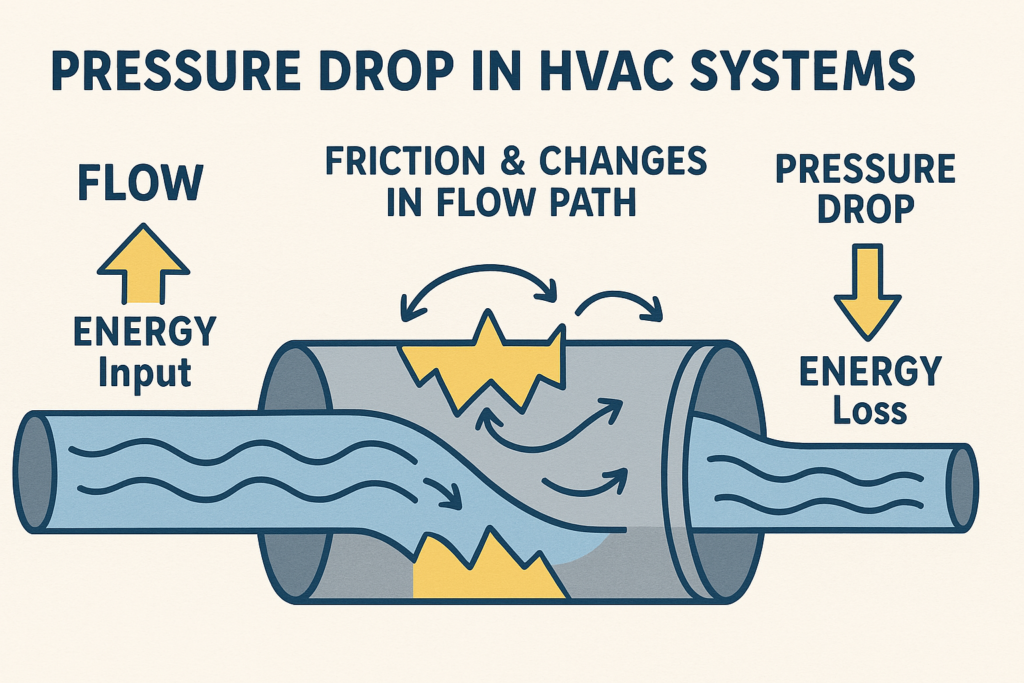
When fluid (like water or air) flows through pipes or ducts in HVAC systems, not all its energy is used for heating or cooling. Some of that energy is “lost” along the way due to friction and changes in the flow path. These losses appear as pressure drops, meaning the fluid loses energy as it travels from one end of the system to the other. Let’s break down these concepts in a way that’s easy to understand!

1. The Big Picture: What Are Energy Losses in Fluids? 🔋💧

Every time fluid flows, it carries energy in the form of kinetic energy (because of its velocity) and potential energy (if there’s a change in elevation). However, as the fluid flows through a pipe or duct, friction with the pipe walls and disturbances from bends, valves, and fittings turn some of that energy into heat. This process reduces the pressure available downstream. In HVAC systems, understanding and controlling these losses is key to efficient design.


2. Friction Loss in Pipes: The Darcy-Weisbach Equation 🛠️📏

Friction losses occur because fluid rubbing against the inner walls of a pipe experiences resistance. A common way to calculate these losses is with the Darcy-Weisbach equation. The equation gives you the “head loss” (the drop in pressure expressed as an equivalent height of fluid) due to friction:

Here’s what each term means:

  • HL: Head loss (in meters, m) – this is the energy loss per unit weight.
  • f: Darcy friction factor (dimensionless) – a factor that depends on whether the flow is laminar or turbulent and on the roughness of the pipe’s interior surface.
  • L: Length of the pipe (m) – the longer the pipe, the more friction the fluid experiences.
  • D: Pipe diameter (m) – narrower pipes create higher velocity (for the same flow rate), which increases friction.
  • V: Average fluid velocity (m/s) – faster flow increases energy loss.
  • g: Acceleration due to gravity (≈9.81 m/s²) – a constant that helps convert energy terms to “head.”

Example:
Imagine water flowing through a 50-meter-long pipe with a diameter of 0.1 m at an average speed of 2 m/s. If the friction factor f is 0.02 (typical for a smooth, turbulent flow), the head loss is calculated as:

This means the fluid “loses” energy equivalent to a 2-meter drop in height as it flows through the pipe.

3. Fitting Losses: More Than Just Long Pipes 🚧🔧

Besides friction in the straight sections of a pipe, every time a fluid changes direction or passes through a device (like a valve, bend, or contraction) there are extra losses called fitting losses. Flow disturbances like separations or changes in the velocity profile cause additional energy dissipation.

These losses can be estimated using a loss coefficient K:

Where:

  • K: Loss coefficient (dimensionless) – This number is determined experimentally and varies with the type and geometry of the fitting. For example, a well-rounded entrance might have K of 0.05, a 90° miter elbow might be around 1.3, and a partially open valve could even have a K value as high as 28.8!
  • V and g: As defined earlier.

How it works:
If your system includes several fittings, each fitting contributes its own energy loss. To determine the total energy loss from these fittings, simply add all the individual losses together.

Total Head Loss in the System:
Both friction in the pipe and fitting losses add up. So, the total head loss Htotal is:

This equation tells us that to reduce energy losses, you can:

  • Increase the pipe diameter (which reduces V for a given flow rate)
  • Use smoother pipes to reduce the friction factor f
  • Minimize the number of fittings or use designs with lower K values (like well-rounded elbows and optimized valves)
Section 1: Friction Loss Basics

When fluids move through pipes or ducts, they lose energy due to friction with the walls. This frictional loss causes a decrease in the fluid’s pressure as it travels through the system.

For example: The energy loss in a pipe may be calculated using the Darcy-Weisbach equation:

HL = f (L/D) (V2 / 2g)

  • HL: The head loss (energy loss expressed as an equivalent height of fluid).
  • f: Darcy friction factor (depends on the flow regime and pipe roughness).
  • L: Length of the pipe.
  • D: Pipe diameter.
  • V: Average fluid velocity.
  • g: Acceleration due to gravity (≈9.81 m/s²).

This equation shows that longer pipes, smaller diameters, and higher velocities all result in more frictional energy loss.

Section 2: Fitting Losses Explained

In addition to friction along straight sections, energy is lost when fluid flows through changes in direction or area. These include elbows, valves, contractions, and expansions.

The extra loss is often quantified by a loss coefficient K as follows:

Loss = K × (V2/2g)

Every fitting (e.g., a sharp elbow or partially opened valve) has a characteristic K value. For instance, a well-rounded entrance might have K ≈ 0.05, whereas a 90° mitered elbow might have K ≈ 1.3. When multiple fittings are used, simply add their losses to the frictional loss.

Section 3: Combining Friction and Fitting Losses

Engineers must often consider both friction loss and fitting losses together when designing an HVAC system. The overall energy loss (or total head loss) is the sum of the losses due to pipe friction and those due to fittings:

Htotal = [f (L/D) + ΣK] × (V2/2g)

This total head loss directly impacts the performance of pumps and blowers. Minimizing these losses by using larger, smoother pipes and low-loss fittings can result in significant energy savings and improved system performance.

For example, if a duct system contains long runs combined with several elbows and a control valve, accurate loss calculations allow you to size the blower correctly to ensure efficient operation.

Fittings Head Loss Calculator

Enter the number of each fitting used and the average fluid velocity (in m/s) below. The calculator uses the loss equation:

Head Loss = (ΣK) × (V² / (2 × 9.81))

Fitting Type Default K Value Quantity
Sharp Entrance 0.5
Well-Rounded Entrance 0.05
Sharp Contraction 0.38
90° Miter Elbow 1.3
Short Radius Elbow 0.9
Long Radius Elbow 0.6
Globe Valve (Open) 10
Angle Valve (Open) 5
Gate Valve (Open) 0.2
Tee (Straight-Through) 0.5
Tee (Branch Flow) 1.8

Total Head Loss Calculator

The Friction Factor (f) is a dimensionless parameter that quantifies the resistance to flow along a pipe wall. It is used in the Darcy–Weisbach equation to determine energy loss due to friction. In laminar flow, f = 64/Re; for turbulent flow, f depends on the Reynolds number and the pipe's surface roughness. You can select a common pipe type below to pre-set this value.

4. Why Do These Losses Matter? 🏗️📉

Reducing pressure loss is crucial because pumps and blowers must work harder to overcome these losses. This results in higher energy consumption and can affect overall system performance. By understanding the origins of these losses:

  • Engineers can design more efficient systems: Choosing the right size for pipes and selecting low-loss fittings reduces operational costs.
  • It aids in troubleshooting: If a system isn’t delivering the expected airflow or pressure, knowing how and where energy is lost can help pinpoint issues.

5. Tips for Minimizing Energy Losses in HVAC&R Systems ⚙️💡

  • Use Larger Pipes When Possible: A larger diameter reduces the velocity of the fluid (for the same flow rate) and thus lowers friction losses.
  • Select Smooth Pipe Materials: Smoother surfaces decrease the friction factor fff.
  • Optimize Fittings: Use fittings with low K values, and design duct and piping layouts that minimize abrupt changes in direction.
  • Incorporate Diffusers and Gradual Transitions: These help the flow gradually adapt, reducing separation and associated losses.
  • Maintain Your System: Over time, roughness may increase due to fouling or corrosion. Regular maintenance keeps the system operating efficiently.

Leave a Comment