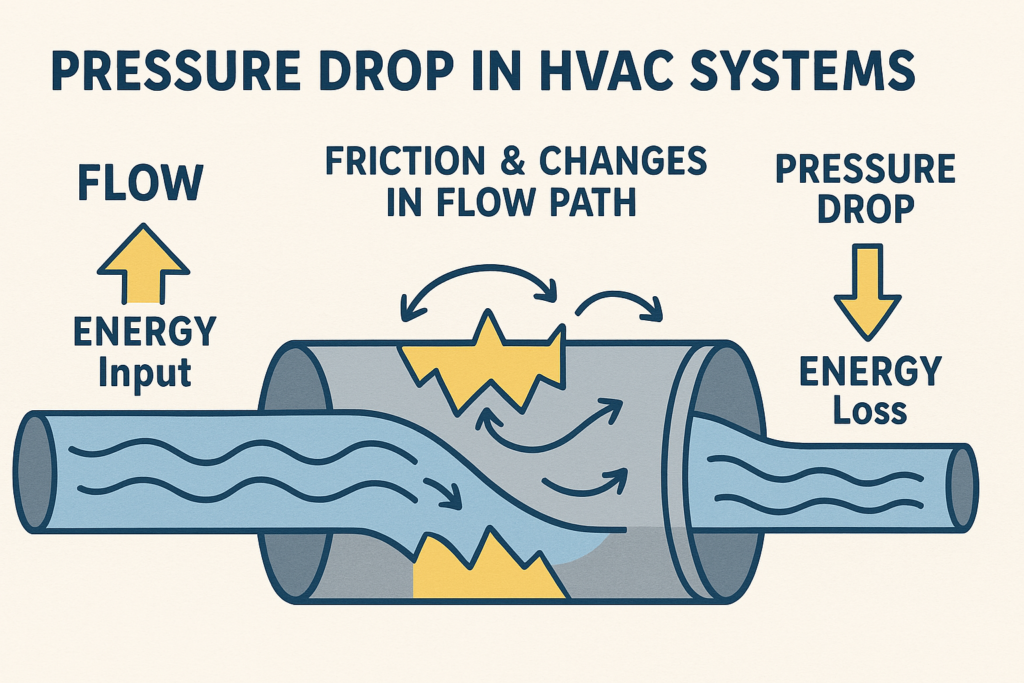
Friction and Fittings

How Flow Loses Energy: Friction and Fittings in Real Systems šŸš°šŸ’”

Views in the last 30 days: 54

Estimated read time: 6 minute(s)

Multi‑Section Head Loss Calculator (Pipes + Fittings)

Build as many sections as you need, each with its own pipe length, diameter, material (roughness), friction‑factor method, velocity, and fittings. Then compute the total head loss and pressure drop. Change –accent above to match your palette.

1) Global settings

3) Results

–
–
–
Pressure vs Distance (EGL/HGL)Adds slope per section and steps for fittings

Energy Losses in Pipes & Ducts (HVAC): Darcy–Weisbach Made Easy

Not all flow energy makes it to the diffuser or coil—friction and fittings turn some into heat, seen as pressure drop. Here’s a clear, step‑by‑step explainer with worked example and fitting‑loss integration.

1) The Big Picture: What Are Energy Losses in Fluids? šŸ”‹šŸ’§

When fluid (like water or air) flows through pipes or ducts, it carries energy as velocity (kinetic) and sometimes elevation (potential). As it travels, friction with the wall and disturbances from elbows, valves, dampers, and tees convert some of that energy into heat. We perceive that conversion as a pressure drop from one end to the other. In HVAC, predicting and managing these losses is central to efficient design.

Rule of thumb: Long runs, small diameters, high velocities, and rough materials all increase loss.

3) Fitting Losses: More Than Just Long Pipes šŸš§šŸ”§

Besides friction in straight runs, every direction change or device (valves, elbows, tees, contractions/expansions) adds fitting losses. Flow separation and profile changes dissipate extra energy.

Fitting loss equation: Loss = K (V^2 / 2g)
K (–)
Loss coefficient measured from experiments; depends on fitting type/geometry.
Examples
Well‑rounded entrance ā‰ˆ 0.05; 90° miter elbow ā‰ˆ 1.3; partially‑open valve can be ≫ 1 (e.g., 28.8).
Summation
Total fitting loss = Ī£ Ki (V²/2g). Add each fitting’s contribution.
Citation: Fitting‑loss equation image (image‑70.png)

4) Total Head Loss in the System

Friction and fitting losses add together to give the total head loss:

Total head loss equation: H_total = f (L/D) (V^2/2g) + Σ K (V^2/2g)
Citation: Total‑loss equation image (image‑71.png)
How to reduce losses (quick wins)
  • Increase pipe/duct diameter → lowers velocity V for a given flow rate, reducing both friction and K‑loss terms.
  • Use smoother materials → decreases friction factor f.
  • Minimize fittings or choose low‑K designs → long‑radius elbows, well‑rounded entries, optimized valves.

5) Worked Example

Given: L = 50 m, D = 0.10 m, V = 2 m/s, f = 0.02 (smooth turbulent), g = 9.81 m/s².

  1. Compute L/D = 50 / 0.10 = 500
  2. Compute V²/(2g) = 2² / (2Ɨ9.81) = 4 / 19.62 = 0.2039
  3. Head loss HL = f Ɨ (L/D) Ɨ V²/(2g) = 0.02 Ɨ 500 Ɨ 0.2039 = 2.04 m
Numerical substitution of Darcy–Weisbach example resulting in HLā‰ˆ2 m
Citation: Example image (image‑69.png)
Convert head loss to pressure drop Δp

If you want Ī”p, multiply by ρg: Ī”p = ρ g HL.

  • Water (~1000 kg/m³): Ī”p ā‰ˆ 1000Ɨ9.81Ɨ2.04 ā‰ˆ 20,000 Pa (ā‰ˆ20 kPa).
  • Air (~1.21 kg/m³): Ī”p ā‰ˆ 1.21Ɨ9.81Ɨ2.04 ā‰ˆ 24 Pa.

Same head loss gives a much smaller pressure drop in air because ρ is low.

6) How do I get f?

Calculate Reynolds number Re = V·D/ν. Then use:

  • Laminar (Re < 2300): f = 64/Re
  • Turbulent: Use Moody chart or the Swamee‑Jain formula f = 0.25 / [log₁₀((ε/D)/3.7 + 5.74/Re⁰·⁹)]²

Need fundamentals first? See Continuity Equation: HVAC Duct Flow and Understanding Fluid Properties.

7) Common Pitfalls & Pro Tips

  • Don’t forget fittings—they often dominate losses in short runs. Use Ī£K or equivalent lengths.
  • Keep an eye on velocity (noise/comfort): trunks ā‰ˆ 5–6 m/s, branches ā‰ˆ 3.5–4.5 m/s, terminals ā‰ˆ 1.5–2.5 m/s.
  • Use internal diameter (clear duct size) and consistent units.
  • Verify roughness by material: galvanized ~152Ɨ10⁻⁶ m; steel ~46Ɨ10⁻⁶ m; smooth ~1.5Ɨ10⁻⁶ m.

8) Related Reading

HVAC Head Loss Basics — Quick Accordion

When fluids move through pipes or ducts, they lose energy due to friction with the walls. This frictional loss causes a decrease in the fluid’s pressure as it travels through the system.

For example: The energy loss in a pipe may be calculated using the Darcy–Weisbach equation:

HL = f (L/D) (V2 / 2g)

  • HL: Head loss (energy loss expressed as an equivalent height of fluid).
  • f: Darcy friction factor (depends on the flow regime and pipe roughness).
  • L: Length of the pipe.
  • D: Pipe diameter.
  • V: Average fluid velocity.
  • g: Acceleration due to gravity (ā‰ˆ9.81 m/s²).

This equation shows that longer pipes, smaller diameters, and higher velocities all result in more frictional energy loss.

In addition to friction along straight sections, energy is lost when fluid flows through changes in direction or area. These include elbows, valves, contractions, and expansions.

The extra loss is often quantified by a loss coefficient K as follows:

Loss = K \u00d7 (V2 / 2g)

Every fitting (e.g., a sharp elbow or partially opened valve) has a characteristic K value. For instance, a well‑rounded entrance might have K ā‰ˆ 0.05, a 90° mitered elbow K ā‰ˆ 1.3, and a partially open valve can be much higher. When multiple fittings are used, simply add their losses to the frictional loss.

Engineers must often consider both friction loss and fitting losses together when designing an HVAC system. The overall energy loss (total head loss) is the sum of the losses due to pipe friction and those due to fittings:

Htotal = [f (L/D) + Ī£K] Ɨ (V2 / 2g)

This total head loss directly impacts the performance of pumps and blowers. Minimizing these losses by using larger, smoother pipes and low‑loss fittings can result in significant energy savings and improved system performance.

For example, if a duct system contains long runs combined with several elbows and a control valve, accurate loss calculations allow you to size the blower correctly to ensure efficient operation.

Leave a Comment