NFPA 13 Equivalent Length Calculator for multi-segment sprinkler paths—compute friction loss, fittings, SI/US units, costs, and one-click reports.
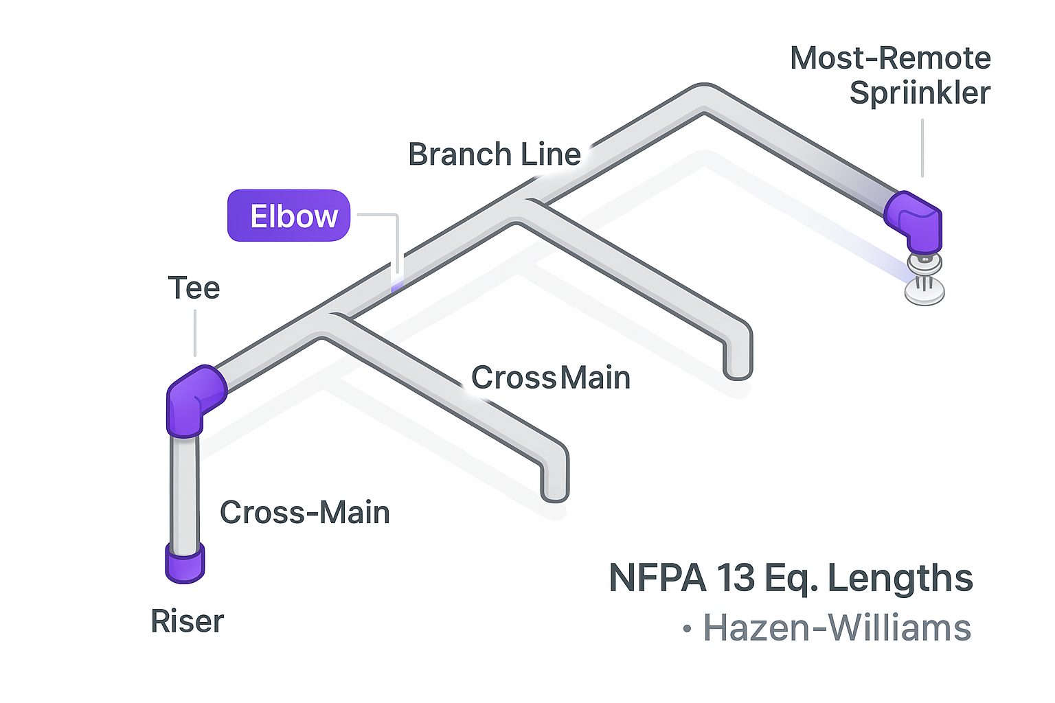
NFPA 13 Equivalent Length Calculator for multi-segment sprinkler paths—compute friction loss, fittings, SI/US units, costs, and one-click reports.

