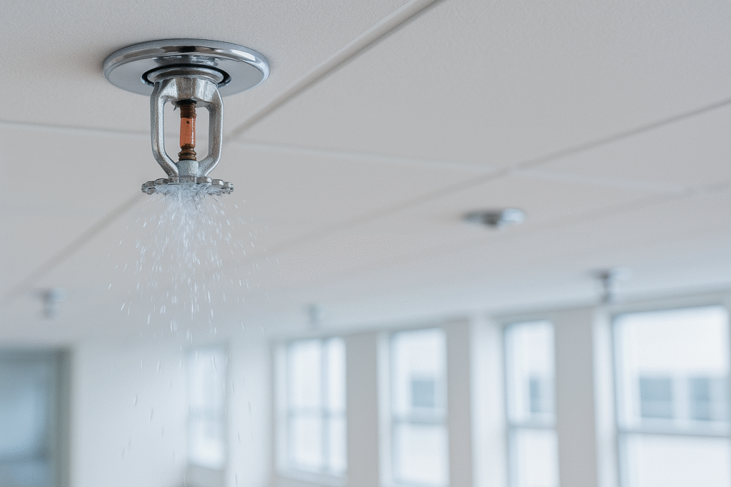
Sprinkler System: Types, Components & How It Works

Views in the last 30 days: 71

Estimated read time: 8 minute(s)

💦 What Is a Sprinkler System? Types, Components, and How It Works

Simple, no‑fluff primer — perfect for students and first‑time designers. Includes mini calculator, comparisons, and quick quizzes.

🔥 Introduction: Why Sprinkler Systems Matter

Every year, thousands of buildings are saved from devastating fires thanks to one silent hero — the sprinkler system. But what exactly is it? How does it know when to go off? What are the different types? Let’s break it all down in simple, no‑fluff language — perfect for engineering students or anyone new to fire protection! 🧑‍🎓

NFPA 13 Definition (highlight): “A sprinkler system consists of an integrated piping network designed in accordance with fire protection engineering standards that includes a water supply, control valve, waterflow alarm, and sprinklers arranged in a systematic pattern.”

Edition note: Wording may vary slightly by edition — always check the specific text in your adopted code.

🧠 What Is a Sprinkler System?

A sprinkler system is a network of pipes and devices designed to automatically spray water when it detects heat from a fire. Think of it as the building’s emergency fire brigade — on duty 24/7! 🚨

🧰 Main Components of a Sprinkler System

SprinklersThe nozzles that spray water over the fire area.
PipesDistribute water to sprinklers (wet or dry).
Control ValveTurns the water supply on or off.
Waterflow AlarmNotifies when the system activates.
Water SupplyCity main, tank, or pump source.
System RiserVertical connection from supply to piping.

🔄 How Does a Sprinkler System Work?

  1. 🔥 Fire starts → Heat rises
  2. 🌡️ Heat activates sprinkler head (around 57–74 °C typical)
  3. 🚿 Water sprays over fire
  4. 💦 Fire gets suppressed or controlled
  5. 🔔 Alarm notifies people or fire department

Note: Only nearby sprinklers activate — not the whole building!

Tap to see heat → spray effect.

🧪 Types of Sprinkler Systems (NFPA 13)

Wet Pipe
  • Most common, instant water flow.
Dry Pipe
  • Used in freezing zones; air in the pipe, water at the valve.
Preaction
  • Requires heat + detector; great for museums/IT rooms.
Deluge
  • All heads open; water dumps when detection trips — high‑hazard areas.
Antifreeze
  • Contains listed freeze‑resistant solution for small sections.
ESFR
  • Early Suppression Fast Response — for warehouses; often eliminates in‑racks when criteria met.
CMSA
  • Control Mode Specific Application — tailored to high‑challenge hazards like plastics.

📐 Density/Area Method: The Basic Calculation

Formula: Flow (Q) = Density (D) × Area (A)

Result: — L/min • — gpm
Density mirror: — mm/min • — gpm/ft²

Hint: 1 gpm/ft² ≈ 40.745 mm/min. In metric, Q(L/min) = D(mm/min) × A(m²).

📊 Wet Pipe vs Dry Pipe Comparison

FeatureWet PipeDry Pipe
Water in PipesYesNo
Cost💲 Lower💲💲 Higher
Response TimeFasterSlight Delay
MaintenanceLowerHigher

📏 NFPA 13 vs 13R vs 13D

NFPA 13

Commercial/Industrial buildings (full protection).

NFPA 13R

Residential up to 4 stories.

NFPA 13D

One‑ or two‑family homes.

60‑Second Check

Score: 0/3

Q1. In metric units, the flow for 10 mm/min over 200 m² is…


Q2. Which system is typically used in freezing areas?


Q3. ESFR sprinklers primarily aim to…


These are learning prompts only — always follow NFPA 13 and the manufacturer’s listing data.

Need a purple theme? Set style="--accent:#8b5cf6" on the wrapper.

Riser Check Valve Assembly (Detail‑A) — Annotated Explainer

Zoomable diagram on the left; in‑depth component notes on the right. Built for quick learning and field reference.
Open full size

Detailed Notes & Functions

Automatic Air Vent (15 mm)
  • Function: Purges trapped air at the high point of a wet riser to reduce corrosion risk, water hammer, and nuisance alarm gong operation.
  • What to know: Usually installed with a small isolating valve for service. Ensure the vent discharge goes to a safe drain or drip cup.
  • Signs of trouble: Frequent air discharge or continual water drips may indicate micro‑leaks letting air in or pressure fluctuations.
15 mm Isolating Valve (for vent/auxiliary lines)
  • Allows maintenance of the vent or trim without shutting the main riser.
  • Keep normally open; tag position during inspections.
Hose Supply Line Tee (branch to Offices)
  • Branches from the main riser to supply hose reels/landing valves serving offices (ground & first floors in this detail).
  • Confirm valveing, pressure regulation, and signage as per local code/standard.
Ø80 Standpipe / Hose Riser
  • Vertical pipe feeding hose outlets; may be part of a combined sprinkler/standpipe system.
  • Verify hydraulics for required residual pressure and flow at the most remote hose outlet.
Flow Switch
  • Senses water movement when a sprinkler opens; sends an alarm signal after a short retard (to avoid false trips from surges).
  • Wire to the fire alarm control panel; label zone/area clearly.
  • Test: Operate via the inspector’s test connection; verify alarm at panel and any local annunciation.
Water Motor Alarm Gong/Bell
  • Hydraulically driven bell that sounds when the alarm trim fills (no power needed).
  • Mount where it’s audible outdoors; ensure drain return to prevent icing or water staining on walls.
Retard Chamber & Pressure Switch
  • Retard chamber: Catches small pressure surges so the water gong doesn’t ring falsely.
  • Pressure switch: Electrical alarm input to the panel when the alarm line is pressurized.
  • Drain the chamber after tests; clogged orifices cause delayed or continuous alarms.
Alarm Check Valve (ACV)
  • Primary one‑way valve separating supply from system. Opens on legitimate system flow and simultaneously feeds the alarm trim.
  • Prevents reverse flow/backspin of meters; helps maintain system pressure.
  • Watch the pressure differential between upstream and downstream gauges; an excessive drop may indicate a partially open clapper or obstruction.
Pressure Gauges (Upstream & Downstream)
  • Provide quick indication of static (no flow) and residual (flow) pressures during main‑drain or alarm tests.
  • Use to diagnose supply issues or a leaking clapper (slow equalization without demand).
  • Calibrate/replace per inspection standard intervals.
Inspector’s Test & Drain Valves
  • Simulates one sprinkler operation via an orifice; verifies alarm actuation and water delivery path.
  • Test water should be visible/discharged to a safe location; keep signage and valve positions clear.
Main Drain Valve
  • Full‑size drain used for acceptance & periodic tests. Measures static vs residual pressure to assess supply performance.
  • Record time to restore static after closing as a health indicator; slow recovery may point to restriction/backflow issues.
Double‑Check Backflow Preventer
  • Stops contaminated water from returning to the potable/main supply. Typically required by water authorities.
  • Is a testable device; expect a measurable pressure loss across it. Provide clearance for annual testing and maintenance.
Flange Connection
  • Bolted joint allowing the assembly to be removed or components replaced.
  • Select gasket & bolt materials to match pressure class and corrosion environment.
Reducer (80×100) & Sway Braces
  • Transitions between pipe sizes while maintaining flow velocity within design limits.
  • Sway braces/hangers stabilize the riser; place per seismic/support rules to resist lateral movement.
Incoming 100 mm Ductile‑Iron Fire Service
  • Feed from the site’s underground fire main into the riser assembly.
  • Coordinate with exterior isolation (e.g., post indicator valve) and provide thrust blocks/anchors where required.

Quick Troubleshooter

  • Alarm gong rings randomly: Check for pressure surges; confirm retard chamber orifice isn’t blocked and air vent is functioning.
  • Large pressure drop across ACV at no flow: Debris at clapper seat or partially stuck check — schedule maintenance.
  • Slow water during inspector’s test: Verify main drain reading vs historical; check backflow device for excessive loss or closed valves.
  • Persistent air in system: Confirm automatic air vent location and isolation valve position; look for suction at pump or micro‑leaks.

Inspection & Testing Pointers

  • Record static/residual at each main‑drain test and trend over time.
  • Test flow switch & pressure switch from the inspector’s test connection.
  • Exercise isolation valves and verify tamper monitoring where provided.
  • Keep gauge calibration up to date; replace damaged or out‑of‑tolerance gauges.

Use your adopted edition of NFPA 25 for exact inspection/testing intervals.

Want a purple palette? Set style="--accent:#8b5cf6" on the wrapper.

Leave a Comment