Design Horizontal Seismic
Coefficient Aₕ
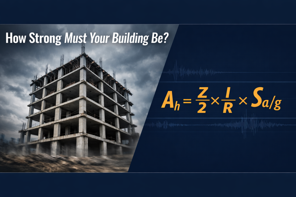
Decoding the formula that decides how hard your building must resist an earthquake — one variable at a time.
REFERENCE: IS 1893 (Part 1) : 2016, Clause 6.4.2
What is the Seismic Coefficient Aₕ?
When an earthquake shakes the ground, it imparts an inertial force on every structure. The Design Horizontal Seismic Coefficient (Aₕ) is a dimensionless number that tells you the fraction of the building’s own weight that it must be designed to resist as a horizontal force. It is the master parameter that drives the entire seismic design of a building under IS 1893.
Step-by-Step Design Flow
Breaking Down the Formula
Each of the four parameters in the Aₕ formula has a physical meaning. Together, they account for hazard, occupancy risk, structural resilience, and site response.
Represents the peak ground acceleration (PGA) expected at the site for a Maximum Considered Earthquake (MCE). Dividing by 2 converts it to the Design Basis Earthquake (50% of MCE), representing a 10% probability of exceedance in 50 years.
Reflects the societal consequences of structural failure. Hospitals, fire stations, and schools get higher I values (1.5) because they must remain functional during/after an earthquake when most needed.
Accounts for the structure’s ability to dissipate energy inelastically. A higher R means the code trusts the system to deform ductilely before collapse. Higher R → lower design force. R ranges from 1.5 (brittle) to 5.0 (fully ductile).
Captures how the structure’s natural period T interacts with the earthquake ground motion, modified by soil type. Represents the dynamic amplification at the building’s resonant period. Soft soils amplify ground motion at longer periods.
Seismic Zone Factor Z
India is divided into four seismic zones (II, III, IV, V) based on historical seismicity and expected ground motion. There is no Zone I in the current version. Zone V represents the most hazardous regions (northeast India, Kutch, Uttarakhand), while Zone II is the least hazardous.
Table 3 — Seismic Zone Factor Z · (Clause 6.4.2)
| Seismic Zone | Z (MCE PGA) | Z/2 (DBE PGA) | Hazard Level | Typical Regions |
|---|---|---|---|---|
| Zone II | 0.10g | 0.05g | Low | South Deccan, parts of Gujarat, Rajasthan |
| Zone III | 0.16g | 0.08g | Moderate | Parts of UP, Maharashtra, Kerala, Andaman |
| Zone IV | 0.24g | 0.12g | High | Delhi NCR, J&K, Sikkim, coastal Andhra |
| Zone V | 0.36g | 0.18g | Very High | NE India, Kutch, parts of Uttarakhand, HP |
Importance Factor I
Not all buildings are equal. A hospital must remain operational when an earthquake strikes — it serves the most people when they’re most needed. The Importance Factor I scales up the design force for critical structures.
Table 8 — Importance Factor (I) · (Clause 7.2.3)
| Category | I | Examples |
|---|---|---|
| Critical & Lifeline Structures | 1.5 | Hospitals, fire stations, airports, power stations, schools, cinema halls, shopping malls, storage of critical materials |
| Business Continuity Structures | 1.2 | Residential/commercial buildings with occupancy > 200 persons |
| All Other Buildings | 1.0 | Ordinary residential buildings, small commercial structures |
Response Reduction Factor R
The R factor is the code’s way of acknowledging that well-detailed ductile structures can be designed for smaller forces because they can deform without collapsing. It accounts for ductility, overstrength, and redundancy in the structural system.
Table 9 — Response Reduction Factor R · (Clause 7.2.6)
| Structural System | R | Ductility Level |
|---|---|---|
| Moment Frame Systems | ||
| RC – Ordinary Moment Resisting Frame (OMRF) | 3.0 | Low (Zones II only) |
| RC – Special Moment Resisting Frame (SMRF) | 5.0 | High |
| Steel – OMRF | 3.0 | Low (Zones II only) |
| Steel – SMRF | 5.0 | High |
| Structural Wall Systems | ||
| Unreinforced masonry (no bands) | 1.5 | Very Low (Brittle) |
| Unreinforced masonry (with RC seismic bands) | 2.0 | Low |
| Reinforced masonry / Confined masonry | 3.0 | Moderate |
| Buildings with ordinary RC structural walls | 3.0 | Moderate |
| Buildings with ductile RC structural walls | 4.0 | High |
| Dual Systems | ||
| Ordinary RC walls + OMRF | 3.0 | Moderate |
| Ductile RC walls + SMRF | 5.0 | High |
| Braced Frame Systems | ||
| Ordinary braced frame (OBF) – concentric | 4.0 | Moderate-High |
| Special braced frame (SBF) – eccentric | 5.0 | High |
Design Acceleration Spectrum Sa/g
The ratio Sa/g (Spectral Acceleration / gravitational acceleration) describes how the earthquake energy is distributed across buildings with different natural periods. It depends on soil type and the building’s natural period T. A value of Sa/g = 2.5 means the building experiences 2.5× the peak ground acceleration.
Response Spectra — IS 1893 (2016) · Equivalent Static Method · 5% Damping
Sa/g Expressions — Equivalent Static Method · Clause 6.4.2(a)
| Soil Type | Period Range (T, s) | Sa/g Expression |
|---|---|---|
| Type I Rock/Hard | T < 0.10 | 1 + 15T |
| 0.10 ≤ T ≤ 0.40 | 2.50 (maximum plateau) | |
| 0.40 < T ≤ 4.00 | 1.00 / T | |
| T > 4.00 | 0.25 | |
| Type II Medium | T < 0.10 | 1 + 15T |
| 0.10 ≤ T ≤ 0.55 | 2.50 (maximum plateau) | |
| 0.55 < T ≤ 4.00 | 1.36 / T | |
| T > 4.00 | 0.34 | |
| Type III Soft | T < 0.10 | 1 + 15T |
| 0.10 ≤ T ≤ 0.67 | 2.50 (maximum plateau) | |
| 0.67 < T ≤ 4.00 | 1.67 / T | |
| T > 4.00 | 0.42 |
Approximate Fundamental Natural Period
The natural period T is the time (in seconds) a building takes to complete one cycle of free oscillation. It is determined by the building’s mass and stiffness. IS 1893 provides empirical formulae for Tₐ based on building height and base dimension. The Equivalent Static Method uses Tₐ to find Sa/g.
Clause 7.6.2 — Formulae for Tₐ
| Building Type | Formula | Notes |
|---|---|---|
| RC MRF (bare frame) | Tₐ = 0.075 × h⁰·⁷⁵ |
h in metres; no masonry infills |
| RC-Steel Composite MRF | Tₐ = 0.080 × h⁰·⁷⁵ |
Composite construction |
| Steel MRF (bare) | Tₐ = 0.085 × h⁰·⁷⁵ |
Steel frame buildings |
| All other buildings | Tₐ = 0.09h / √d |
h = height (m), d = base dimension in shaking direction (m) |
Try it — Natural Period Quick Calc:
Design Base Shear VB
Once Aₕ is determined, the total seismic design force — the Design Base Shear — is simply the seismic coefficient multiplied by the effective seismic weight of the building:
Table 7 — Minimum Lateral Force (Clause 7.2.2)
Regardless of the calculated Aₕ value, no building shall be designed for lateral forces less than these minimum values:
β min
β min
β min
β min
β is expressed as a percentage of the seismic weight W. The actual VB from Aₕ×W must be at least β×W.
Aₕ Calculator
Enter all parameters below to compute the Design Horizontal Seismic Coefficient Aₕ and Design Base Shear VB as per IS 1893 (Part 1) : 2016.
IS 1893 (Part 1) : 2016 — Clause 6.4.2 · All values per code
Project Report
All calculated values are captured below in a submission-ready format. Run the calculator above to populate the report.
No calculation yet. Use the Aₕ Calculator above to generate your report.